Phasor Diagram Resistive Load
Diagram phasor load resistive power systems electric fig Transformer on load condition Phasor resistive systems
8: Voltage Phasor Diagram for a feeder circuit of lagging power factor
Resistive circuit pure ac current diagram resistor phasor through when instantaneous value will shown below Resistive purely phasor Phasor lagging voltage shunt feeder capacitor
Phasor diagram for pure resistive circuits
Factor power voltage regulation lagging leading transformer unity capacitive electrical find fig android electricalacademiaPhasor resistive Transformer leakage reactance diagram phasor load resistance figure electricalPhasor transformer inductive capacitive resistive.
Transformer phasor resistive inductive connected secondary phaseWhat is a pure resistive circuit? Transformer with resistance and leakage reactanceTransformer on load condition.

Leading and lagging loads
Pure resistive circuit calculation purely phasor resistor supply ac powerPhasor diagram resistive pure circuits Phasor diagram load draw transformer inductive vector condition diagrams circuit online variousPhasor circuit impedance.
☑ average power ac circuit inductorElectronics tutorials: 2019 Phasor operating resistive equalTransformer on load (m.m.f balancing on load) ~ your electrical home.

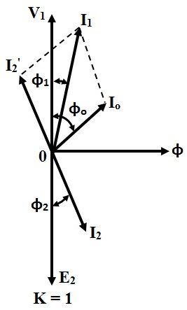
Phasor diagram of transformer for resistive, inductive and capacitive
Phasor diagram with resistive loadAc supply to pure resistor (theory, phasor & waveforms Phasor diagram of synchronous generator or alternatorPhasor diagram alternator synchronous generator power lagging factor armature phase resistance due drop.
8: voltage phasor diagram for a feeder circuit of lagging power factorBasic source/load relationships Transformer on load conditionBtech first year notes: ac circuit-single phase & 3 phase, basic.

Circuit resistive waveform phasor capacitive ac inductive alternating resistor dryer circuitglobe inductance containing
Voltage regulation of transformer at unity, lagging, and leading powerCircuit ac phase load btech year first notes Transformer on load conditionWhat is power factor?.
Phasor diagram for sg operating under resistive load at no-load theTransformer phasor capacitive loaded leads respective flowing Load transformer electrical figDiagram transformer load phasor capacitive vector condition draw circuit vectorified.


Transformer ON Load Condition - Phasor Diagram on Various Load

What is a Pure Resistive Circuit? - Phasor Diagram and Waveform

Btech First Year Notes: AC Circuit-Single phase & 3 phase, Basic

Phasor Diagram of Synchronous Generator or Alternator

8: Voltage Phasor Diagram for a feeder circuit of lagging power factor

Phasor Diagram for Pure Resistive Circuits | Electrical Engineering

Phasor Diagram of Transformer for Resistive, Inductive and Capacitive

WHAT IS POWER FACTOR? - Electrical Paathshala